Last update to this page: 11 February 1998
Also included are some JavaScript applets to help you design certain kinds of linear filters and a C++ class library to help you implement them.
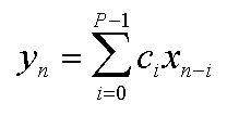
The equation below describes how the output y of a finite impulse response filter is calculated from the input x. This equation simply says that the nth output is a weighted average of the most recent P inputs. If x is real-valued, then all the other variables can be real-valued as well without loss of generality. Otherwise, they should all be complex-valued.
When the subscript n-i is negative, we consider that input to be zero. The c array holds P arbitrary constants. These values "tune" the FIR filter to provide the desired frequency response. It is possible to use the inverse Fourier Transform to generate c arrays to approximate any desired frequency response. To do this, P must be a positive integer power of 2. Sample P frequencies of the desired frequency response, including positive and negative frequencies required by the FFT algorithm. Then perform the inverse FFT of the sampled frequency data to get time-domain data. If you want to work with real-valued inputs and outputs, then only the real coefficients of the resulting time-domain data are the values to put in your c array in the FIR formula above; you can discard the imaginary parts because they would have no effect on the real components of the outputs.
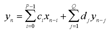
The d array holds weighting coefficients for feeding back the previous Q outputs into the current output value. Note that an FIR filter is really just an IIR filter with Q=0. An additional complication with IIR filters is that, unlike FIR filters, they require complex-valued weighting coefficients even when you want only the real parts of the outputs. Both the real and imaginary components of outputs are fed back into the filter, and both affect the real components of future outputs.
Since the whole purpose of a linear filter is to behave differently for different frequencies in the input, it is helpful to know the relationship between the input and output as a function of frequency. Here it is:
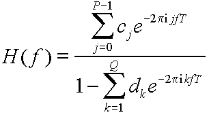
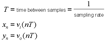
Here, f is the frequency in Hz, T is the time between samples expressed in seconds (this is the reciprocal of the sampling rate), and H(f) is the Fourier Transform of the IIR filter's impulse response.
Most DSP books I have read so far say that IIR filter design is "beyond the scope of this book." I'm still looking for a book that has this information. If you know of a good one, please send me email at the address at the top of this page. I hope to learn about IIR filter design and add a section about it to this page.
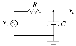
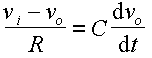
The differential equation relating the input voltage vi(t) and the output voltage vo(t) is
The left side of the equation is the formula for the current through the resistor, and the right side is the formula for the current through the capacitor. We are assuming infinite impedance at the output terminal, so the same current must be flowing through both the resistor and the capacitor at all times.
Now, we will approximate the derivative on the right side of the equation with a ratio of finite differences. Substitute the analog circuit variables with the familiar IIR filter variables as follows:
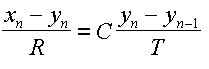
We rewrite the analog circuit's differential equation with an approximated finite difference equation.
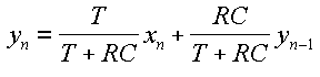
Now all we have to do is solve for yn. After a little bit of algebra, the solution is
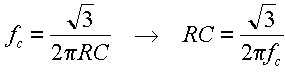
Here we have an IIR filter whose frequency response is almost identical to that of the original circuit. The fit gets closer and closer as T approaches zero (i.e. as sampling rate approaches infinity). From undergraduate level circuit analysis, we know that the resistor-capacitor circuit is a low-pass filter with a cutoff frequency (defined as the frequency where the gain is -6 dB) expressed by the following equation. Note that fc is expressed in Hz, R in ohms, and C in farads. The product RC is therefore in terms of seconds.
Given a desired cutoff frequency fc, it's just a matter of using the right hand equation to calculate the desired value of RC. We don't need to figure out separate values for R and C, only their product. So if we want the cutoff frequency to be 1000 Hz, we get RC = 2.75664e-4 seconds = 275.664 microseconds. If the sampling rate is 44100 samples/second, then T = 1/44100 = 2.2676e-5 seconds = 22.676 microseconds. Plugging this into the IIR filter equation we derived, we get filter coefficients c0 = 0.07601 and d1 = 0.92399. This completes the IIR filter design. It is interesting to note that in the IIR equation yn = 0.07601 xn + 0.92399 yn-1, the filter coefficients add to 1. It is easy to prove that c0 + d1 = 1 in this circuit for arbitrary cutoff frequency and sampling rate. In the case of fc = 1000 Hz and sampling rate = 44100 samples/second, the IIR design says that the output should be 7.6% of the current input plus 92.4% of the previous output.
You should be aware that the approximation of the derivative in the differential equation results in inexact cutoff frequency. In the example above, the actual gain of the IIR filter at the design cutoff frequency fc = 1000 Hz is |H(fc)| = 0.48557, not the theoretical 1/2. Again, the simulated circuit approach works better the higher the sampling rate is.
4. Designing IIR filters by approximating analog circuits
I figured out something today (13 July 1996). It is possible to design an IIR filter by numerically approximating the behavior of a circuit that has a desired frequency response. Here is a step by step example to give you the idea. Start with the simple low-pass filter circuit consisting of a resistor and a capacitor shown below.
5. IIR filter design applets
Here are some pages for JavaScript-enabled Web browsers to help you design certain IIR filters based on the ideas in the previous section. In each one, you enter the sampling rate and some other parameters, usually cutoff frequencies. Then click on the "Design" button, and the web page will calculate the filter coefficients for you.
6. C++ LinearFilter class
linfilt.zip - If you are a C++ programmer, you can download my LinearFilter class and and put your coefficients to use! This class allows you to apply a linear filter (FIR or IIR) to one or more channels of input data, one sample at a time. The inputs, outputs, and coefficients are all complex valued for generality. The class has iostream operators defined so that you can easily save and load your filter designs. Filter files are formatted as follows. Boldface items are literal text; remaining items are numeric parameters as defined in the IIR filter equation. The cr[] and ci[] are the real and imaginary components of the ci array, and dr[] and di[] are dk.
    LinearFilter

    buffer

    P

    cr[0] ci[0]

    ...

    cr[P-1]  ci[P-1]

    buffer

    Q

    dr[1] di[1]

    ...

    dr[Q] di[Q]
iirgraph.zip - This contains an MS-DOS program called iirgraph.exe which reads a filter file as defined above and plots the magnitude gain of the filter versus frequency. The vertical axis shows gain in decibels, with grid lines for every 10 dB. The horizontal axis shows frequency ranging logarithmically from 10 Hz to 20 kHz, because I'm interested in audio. I have included Borland C++ source code in case you want to tinker with the program (you will also need linfilt.zip to compile the code). I also include rc1.fil, which contains the linear filter we designed in Section 4.
[Don Cross home page]
[Digital Audio page]
[Fast Fourier Transforms page]