
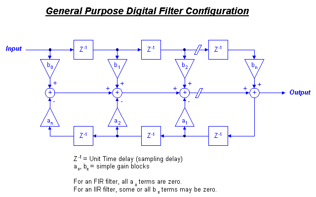
Figure 1 shows the basic structure for a general purpose digital filter. The structure is composed of Z-domain delay blocks, gain stages and summing junctions. Observation of this structure shows how the filter processing each input sample as well as the output. Each time the system samples the input, the top half of the system takes previous input samples and shifts them down the chain of Z
The lower half of the diagram show how the filter can also use the current output value as well as "remember" past output values. These values are also multiplied by fixed coefficients and summed to add into the current output value.
In general, each Z
The choice of an FIR design versus an IIR can spark much debate amoung designers. It is the opinon of the author that new users of digital filters should start out with FIR type filters. This is recommended for the following reasons:
| FIR filters can easily be designed for constant phase delay and/or constant group delay (which affects the distortion of pass band signals with broadband characteristics) |
| Stability is inherent and limit cycling is not a problem as it is with IIR designs (This is provided the User implements the filter with nonrecursive techniques). |
| Round off errors can be controlled in a straightforward fashion in order to keep their effects insignificant |
| An FIR generally requires more stages than an IIR to obtain sharp filter bands. |
| Additional stages add to memory requirements and slow processing speed. |
Designs that demand high performance usually justify an effort to tradeoff FIR vs IIR filter implementations. But for first time application it is recommended that aggressive filter design be avoided until one has the experience to avoid the various pitfalls that await you.
Mathematically, the equation representing the general filter in Figure 1 is:
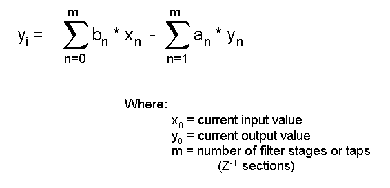
Equation # 1 is straightforward to implement in software or even a spreadsheet. As an example, an FIR filter (lowpass, highpass, or bandpass) would be constructed as follows:
| 1. Determine how many poles are needed and how much ripple in the passband is allowed and how much attenuation in the stop band(s) is required. |
| 2. From this information, compute the coefficients necessary. |
| 3. Setup your software as follows: |
| a. Create an array to hold the incoming input values as a sequence of inputs. Create a matching array to hold the coefficients. |
| b. Set up a software mechanism to add incoming input values to the "x" array. A circular buffer works well for this purpose. |
| c. Set up a function to multiply the current input array by the matching array of coefficients and to then sum the result. That result is the output of your filter. |
Whether you are performing real-time processing or off-line processing, the process is essentially the same. Using a circular buffer is an important means to saving computational time. Without some sort of circular buffer, you must shift the array of input values on each input or you must shift the coefficients. This shifting can be time consuming and may be time reduced dramatically by a circular buffer technique.
Figure 2 shows an example low pass filter. The filter was designed using the Remez Exchange Algorithm to generate the coefficients (explanation of this algorithm is given the following paragraphs). The input signal to the filter was created by combining two sine waves (one near the edge of the passband and one just outside the pass band). Random noise was added to the sine waves. The noise added is uniform in spectrum and thus a portion of the noise power overlaps the passband signals. Thus the filter output still shows some low frequency components riding on the sine wave. This noise could be further reduced by use of a bandpass configuration as would be appropriate in a strictly analog implementation.
It should be apparent at this point that the whole key to these filters is understanding how to generate the coefficients. Implementing the filter itself becomes a small task compared to the mathematics to generate the coefficients.
| Main Page - Introduction | |
| Computing The Coefficients | |
| Additional Functions That Affect The Digital Filter | |
| Summary And References | |
| Digital Filter Program Download |

![]()