
Synthesizers, Music & Broadcasting : T. Yahaya Abdullah
In essence, this is subtractive synthesis. You start with a sound, subtract out the unwanted bits and control its loudness over time.
There are many types of oscillators but the main "Oscillator" usually refers to a "Keyboard-Controlled Oscillator". On a synthesizer, the Keyboard-Controlled Oscillator may be labled as VCO, DCO, or sometimes as Waveform.
All this means is that when you play a note on the keyboard, the oscillator will generate the waveform (or shape) at that intended pitch continuously (for as long as you hold down that note on the keyboard). If you pressed "A3" (the note "A" just below middle "C"), the waveform will be generated at a rate of 440Hz (ie 440 cycles a second). In short, the keyboard controls the pitch of the oscillator (hence, keyboard controlled oscillator) .
A Waveform (or Wave) is a shape which the oscillator generates. The shape determines the "timbre" or quality, characteristic or brightness of a sound. While pitch tells us which note is being played, "timbre" tells us which instrument is being played. While pitch is a basic frequency which identifys the note, "timbre" is made up of many other frequencies or overtones which gives the instrument its overall character and identity.
The basic set of waveforms covered by this document are simple mathematical shapes which are found on analogue synthesizers. The first waveform to look at is the "Sine" wave. Although it is not always available on analogue synthesizers, it is the starting point to understanding waveforms and their "harmonic content" (ie timbre).
WAVE GRAPHS - When we graphically show a waveform cycle (eg Sine Wave), it has two axes: Amplitude (vertical axis) and Time (horizontal axis).
HARMONIC SERIES - A Sine wave is the most basic waveform and is the building block of harmonic analysis. This is because a Sine wave has no harmonics (overtones) at all. It only has the tone of the fundamental frequency and no timbre. The Fundamental frequency is the base or root frequency which we identify as pitch (eg "A3" would be at 440Hz).
Since a Sine wave is pure (no harmonics), we can create other waveforms simply by adding together any number of sine waves at different frequencies and different volume levels (amplitudes).
Mathematically, any sound can be created using Sine waves at different frequencies and amplitudes. Similarly, any sound can be broken down into discrete and distinct Sine waves at different frequencies and amplitudes.
If we look at any static waveform (a pitched sound which doesn't change timbre over time), it is made of sine waves which are Multiples of the Fundamental frequency (F). This is known as the Natural Harmonic Series where the series consists of F, Fx2, Fx3, Fx4, Fx5, Fx6 etc. If you analysed a bright violin sound played at the note "A2" (where F.Freq = 220Hz), it is made of a series of sinewaves at 220Hz, 440Hz, 660Hz, 880Hz, 1.1kHz, 1.32kHz, 1.54kHz and so on.
SPECTRUM GRAPHS - We analyse waveforms using a Harmonic Spectrum (It's a lot like the spectrum analyser on a hi-fi). The Harmonic Spectrum has Amplitude (vertical axis) and Frequency of the sine waves (horizontal axis). To simplify analysis, Frequency is usually expressed as multiples of the fundamental frequency while Amplitude is usually expressed as relative to the fundamental sine wave's amplitude.
WAVEFORMS - Let's look at the harmonic spectrum of the basic waveforms available on subtractive synthesizers. The graph shows Waveforms (left) and Harmonic Spectrum (right). Top to bottom: Tri, Square, Saw, Pulse.
TRIANGLE Wave - Or Tri-wave. It sounds (and looks) a bit like the sine wave but has some hollow-sounding quiet overtones. It is made up of only odd numbered harmonics : F, 3F, 5F, 7F 9F etc. The amplitudes of the harmonic series decreases exponentially.
SQUARE Wave - It has very sharp corners, has a hollow sound with quite strong overtones. It is made up of only odd numbered harmonics : F, 3F, 5F, 7F, 9F etc. The amplitudes of harmonic series decreases steadily.
SAW Wave - Also known as Sawtooth, is available as RampUp or RampDown (which sound the same). It has a very bright and rich sound with strong overtones. It is made up of all harmonics : F, 2F, 3F, 4F, 5F,6F etc. The ampitudes of harmonic series decreases steadily.
PULSE Wave - Also known as Rectangle wave. Its sound depends on how far the Pulse Width deviates from the Square wave. The Pulse Width (period when the wave us "up") is usually expressed as a percentage (of the full wave cycle), so a Square wave is a 50% Pulse. A 10% Pulse and a 90% Pulse sound the same (to all intents and purposes).
Note - The fundamental is usually labled "F". The first harmonic is actually at 2F and the second harmonic is at 3F etc. We usually refer to Odd-Numbered harmonics as being the series F, 3F, 5F, 7F etc; and refer to Even-Numbered harmonics as being the series 2F, 4F, 6F, 8F etc.
LOW PASS FILTERS - The main filter in subtractive synthesis is the Low-Pass Filter (LPF). Low-Pass Filters allows the lower frequencies to pass through unaffected and filters out (or blocks out) the higher frequencies. This is controlled by a parameter labled as "Cut-Off Frequency" (or "Cut-Off" or "Frequency").
CUT-OFF - The Cut-Off Frequency determines the position in the harmonic spectrum where the filter will begin to filter (or block) the higher harmonics (ie frequencies). If the Cut-Off is set to a high position, then the timbre will be bright. If the Cut-Off is set to a low position, then the timbre will be dull.
What does it sound like? Try this! Slowly say the words "Wow, wow, wow". This is what an LPF sounds like as the Cut-Off position moves up the harmonic spectrum and back. The first sound was "wuuu" which is fairly pure and dull. The next sound is "aaaa" which is bright and full of harmonics.
FILTER RESPONSE - The way in which filters block out frequencies beyond the Cut-Off position is not abrupt but is instead a gradual rate (which is more natural). So, the further beyond the Cut-Off position, the more the subsequent frequencies are filtered. This occurs up to a point where all further frequencies are completely filtered out.
In Low-Pass Filters, the gradual rate of filtration (beyond the Cut-Off) is usually available as 4-pole or 2-pole filters (which are 24dB/octave and 12dB/octave respectively). So a 4-pole filter has steeper rate of filtration and will filter out more as compared to a 2-pole filter.
RESONANCE - Resonance is another parameter available in a Low-Pass Filter. Resonance is where the frequencies at the Cut-Off position are boosted (made louder). When a little resonance is introduced, the frequencies around the Cut-Off are boosted a little. With a lot of resonance, the frequencies around the Cut-Off are boosted a lot while the lower frequencies will start to diminish a little. When too much resonance is applied, the frequencies around the Cut-Off are so pronounced that the filter will itself start to oscillate and "howl" (like feedback, but in a tuned way).
HIGH-PASS FILTERS - Another common (but less used) filter in subtractive synthesis is the High-Pass Filter (or HPF). A HPF does the opposite of a LPF. A High-Pass Filter allows the higher frequencies to pass through unaffected and filters out (blocks-out) the lower frequencies.
ENVELOPE PARAMETERS - Nowadays, there are many variations of envelopes available. However, the most common envelope has 4 parameters: (1) Attack time, (2) Decay time, (3) Sustain level, and (4) Release time. This is usually called ADSR Envelope.
Apart from controlling the Amplifier, envelopes can also be used to control other sections of a synthesizer. But for now, let us just look at controlling the Amplifier.
Basically, an ASDR envelope only has 3 loudness (amplitude) levels; zero (off), full (the maximum) and the Sustain level.
Let us look at what happens to an ADSR envelope when a key is pressed on the keyboard {Note - Before any key of pressed, the envelope is at zero and so there is no sound}.
OTHER ENVELOPE TYPES - Apart from the ADSR envelope, there are many other variations but they are usually based on the same principles.
ENVELOPE MODULATOR - We have already seen how the amplifier is triggered by the pressing of the keys on a keyboard but is shaped by an ADSR envelope. You could say that the amplitude is being modulated by the ASDR envelope. But an envelope can also be used to modulate other parameters.
ENV ~MOD~ FILTER CUT-OFF - When the Cut-Off is being modulated by an envelope, it is the same as raising and lowering the Cut-Off in tandem with the envelope shape. When the envelope opens up, the sound is brighter ;and, when the envelope decays, the sound is less bright. This effect is sometimes called a "Filter Sweep" and is used for brass and strings. .
Most synthesizers will have a Filter parameter labled "Envelope Amount" which determines by how much the filter is influenced by the envelope. Some synthesizers only have one envelope which is shared between the amplifier and filter. Some synthesizers have 2 or more envelopes which allows using separate envelopes for amplifier and filter. Some synthesizers also have an "invert" switch with reverses the effect (ie the Cut-Off is lowered by an envelope rise and vice versa).
ENV. ~MOD~ OSC.PITCH - When Pitch of the keyboard-controlled oscillator is modulated by an envelope, the Pitch of the oscillator is raised and lowered by the envelope (shape and amount). This is useful for sounds which do not have a static pitch over time. Synthesizers with this function usually have a parameter labled "Envelope Amount" as well as an "invert" switch (ie the Pitch is lowered by an envelope rise and vice versa).
LOW FREQUENCY OSCILLATOR MODULATOR - A Low Frequency Oscillator (LFO) is a very common Modulator available on most synthesizers. Basically, an LFO is an oscillator which works at a set slow rate (perhaps between 0.1Hz to 10 Hz). Typically, an LFO will have the following parameters: Wave (usu Triangle, Square, Saw, Sine), Rate (the speed of the oscillation) and perhaps Delay (a time delay before the oscillator starts). The normal selection would be to use either Tri or Sine waves because of their regular rises and falls without any sudden jumps (Square and Saw waves have sharp jumps).
LFO ~MOD~ OSC.PITCH - Using an LFO to modulate the pitch of the keyboard-controlled oscillator causes the oscillator's pitch to "wobble" with the LFO. Using a Tri or Sine on the LFO will produce "vibrato" (a smooth up and down varying of the pitch). Using a Square on the LFO will produce a "trill" (a sudden varying of pitch). Using a Saw on the LFO will produce something like an alarm siren.
LFO ~MOD~ FILTER CUT-OFF - Using the LFO to modulate the Cut-Off of the filter causes the Cut-Off to vary with the LFO. Used in extremes, it will sound like a "Wah-wah" sound.
LFO ~MOD~ AMPLIFIER - Using the LFO to modulate the Amplifier causes the loudness to vary with the LFO. Using a Tri or Sine on the LFO will produce "tremolo" (smooth varying up and down of amplitude). Using a Square on the LFO will produce a sharp "gated" sound (ie loud, quiet, loud, quiet etc).
KEYBOARD TRACKING MODULATOR - The keyboard not only controls the pitch of the oscillators but can itself be used as Modulator. Keyboard Tracking (KT) is where the position of the notes being played are used to influence other parameters. KT is sometimes labled as Keyboard Follow or Keyboard Scaling. Keyboard Tracking can best be viewed as either off or a positive amount or an negative amount.
KYBD.TRK. ~MOD~ AMP.ENV. - If a positive amount of Keyboard Tracking was applied to the Amplifier Env., then the higher keyboard notes being played would result in louder notes. Negative KT would mean that higher keyboard notes would be quieter.
KYBD.TRK ~MOD~ FILTER CUT-OFF - If a positive amount of Keyboard Tracking was applied to the Filter Cut-Off, then the higher keyboard notes being played would result in brighter notes. Negative KT would mean that higher keyboard notes would be duller.
KYBD.TRK. ~MOD~ OSC.PITCH - Keyboard Tracking applied to the Oscillator Pitch, is treated differently. Synthesizers with this function usually have amounts from 0% to 100% (where 100% is the keyboard tuned normally). A setting of 0% would mean that playing any key would result in the same note (ie the keyboard is not tracking at all). But a KT set to 50% would result in "quarter-tone tuning" (ie playing semitones on the keyboard results in quarter-notes {the a note exactly in between normal semitones} which is used in arabic music).
VELOCITY MODULATOR - Nowadays, many synthesizers respond to Velocity. As standard, the keyboard transmits information on which note is being played. If Velocity is available, then the keyboard will also transmit information on how hard the note was struck. Velocity information (someimes labled as Velocity Sensitivity) can be used in many ways.
VEL ~MOD~ AMP.ENV. - If Velocity was used to modulate the Amplifier Envelope, then the harder struck kybd notes would result in louder notes (ie larger amplitude envelope). This the most common setting for velocity.
VEL ~MOD~ AMP.ENV.ATTACK TIME - If Velocity was used to modulate the Attack Time of the Amplifier Envelope, then the harder struck kybd notes would result in faster attack times.
VEL ~MOD~ FILTER CUT-OFF - If Velocity was used to modulate the Filter Cut-Off, then the harder struck kybd notes would result in overall brighter notes.
VEL ~MOD~ FILTER CUT-OFF ENV. - If Velocity was used to modulate the Envelope of the Filter Cut-Off, then the harder struck kybd notes would result in making the filter envelope more pronounced. This usually means brighter notes (unless inverted) but the effect would depend on the envelope shape.
TWO DETUNED OSCILLATORS - Where two detuned oscillators are mixed together, the result is still the sum of the waveforms. But this time, the oscillators are not synchronised (ie not perfectly in tune).
LFO -MOD- PULSE WIDTH - When a LFO is used to modulate the Pulse Width, then the Pulse Width will change over time, which means the harmonic amplitudes vary too. This is usually called Pulse Width Modulation or PWM (although not necessarily modulated with a LFO).
As the LFO varies, so will the Pulse Width. The top left graph shows the original Square wave, the middle left graph shows the modulating Tri-wave LFO, and the bottom left graph shows the result. PWM looks and sounds a little bit like two detuned oscillators and is an excellent way to create some movement in a timbre.
CROSS-MODULATION - Cross modulation is where the Pitch of one oscillator is modulated by another oscillator; and both are keyboard controlled oscillators. It is a form of pitch modulation except that the modulating oscillator is "keyboard tuned" (determined by the key pressed on the keyboard). This is also called FM (Frequency Modulation) and is very good for producing bell-like sounds.
RING MODULATION - Ring Modulators are circults which output the "Sum and Difference" of its inputs. If the inputs are two Sine waves at 440Hz and 420Hz, the output would be 860Hz (sum) and 20Hz (difference). Depending on the harmonic content of the input, the output can be very complex and it is generally used for gong-like sounds.
CROSS FILTER MODULATION - A rare feature on synthesizers, Cross Filter Modulation is where the Filter Cut-Off is modulated by a keyboard controlled oscillator. It is a form of Filter Modulation except that the modulating oscillator is "keyboard tuned".
Oscillators and Waveforms
OSCILLATORS - An Oscillator generates a sound. It actually generates a waveform or a shape. The oscillator does this continuously. The rate at which it generates each cycle of the waveform is what we hear as pitch. Pitch is measured in Hertz (Hz) [where one Hertz is one cycle per second].
Note - "Time" is very short. A wave cycle at 440Hz occurs in only 2.27 microseconds.
Note - "Amplitude" is not necessarily in terms of perceived overall loudness but it's relative changes over a cycle (ie a microscopic view) {Perceived loudness is where we draw the graph 10 times taller (vertical axis) and say "Ooh! Yes, it is louder now!"}.

As the Pulse Width deviates from 50%, it sounds increasingly brighter and richer; but as the Pulse Width becomes very narrow, it becomes more thin and nasal. Generally, it is made up of all harmonics : F, 2F, 3F, 4F, 5F etc. The amplitudes of harmonic series decreases but the odd and even numbered harmonics have different amplitudes depending on the Pulse Width.
Harmonic F 2F 3F 4F 5F 6F 7F 8F 9F Triangle 1 - 1/9 - 1/25 - 1/49 - 1/81 Square 1 - 1/3 - 1/5 - 1/7 - 1/9 Saw 1 1/2 1/3 1/4 1/5 1/6 1/7 1/8 1/9 Filters
The Filter section of a synthesizer may be labled as VCF (Voltage Controlled Filter) or DCF (Digitally Controlled Filter). A Filter is used to remove frequencies from the waveform so as to alter the timbre.
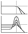 The graphs show Filter Response with Amplitude (vertical axis) and Frequency (horizontal axis). The horizontal dotted lines indicate the "unity gain" level, where the timbre is unaffected. Below this dotted line, the harmonics are filtered (cut); and above the line, the harmonics are boosted. Where the graph is at zero (horizontal axis), the harmonics are completely filtered out.
Top graph = Low-Pass Filter with 4-pole and 2-pole response (4-pole is the steeper sloped).
Bottom graph = LPF with Resonance and shows the filter response as Resonance is increased.
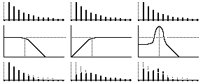 Top graphs show the filter responses. Left to right: Low-Pass Filter; Resonance; and, High-Pass Filter. Cut-Off is indicated by vertical dotted lines.
Middle graphs - harmonic spectrums of the original waveform.
Bottom graphs - harmonic spectrums of the resultant waveforms (affected by the filters).
Envelopes
AMPLIFIER ENVELOPE - The amplifier section on a synthesizer may be labled as VCA (Voltage Controlled Amplifier) or DCA (Digitally Controlled Amplifier). An Amplifier uses an Envelope to control the overall loudness (or amplitude) of the sound over time. Envelopes are activated by pressing the keys on a keyboard.
Attack time it the time taken from zero to full.
Decay time is the time taken from full to Sustain level.
Release time is the time taken from Sustain level to zero.
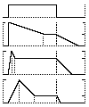 ASDR EXAMPLES - For amplifier envelope, the graphs show Amplitude (vertical axis) and Time (horizontal axis).
Top - shows key-pressed and key-released information (also called "Gate", equivalent to ADSR = 0%, NA, 100%, 0%).
Second ADSR = 0%, 80%, 50%, 60%. Perhaps for Piano.
Third ADSR = 10%, 20%, 75%, 40%. Perhaps for Strings.
Bottom ADSR = 20%, 40%, 25%, 20%. Perhaps for Brass.
One variant with 2 decays is the ADBDSR envelope; Attack, Decay-1, Break-Point, Decay-2, Sustain, Release [where Decay-1 is from full to the Break-Point level; and Decay-2 is from Break-Point level to Sustain level].
Another variant would be something like Rate-1, Level-1, Rate-2, Level-2, Rate-3, Sus, Rate-4 where the envelope is very flexible (Rate is the inverse of Time). Rate = High (a fast rate) is equivalent to Time = Low (a short time).
Modulation
To "modulate" is to exert control or affect or influence or shape. Modulation is used to breathe more life into a sound and make it more expressive. Modulation has 2 components; the Modulator and the Carrier. As an example, if you were humming a note and you used your hand to vibrate your throat, then your hand would be the Modulator and your humming would be the Carrier.
Advanced Waveforms
MIXED WAVEFORMS - Many synthesizers allow two or more oscillators to be mixed together. The resultant waveform is simply the sum of the waveforms (ie both added together). The resultant harmonic series would also be the sum of the harmonics.
Some synthesizers only have on/off switches for its various selectable waveforms. Switching on two or more waveforms will produce a new waveform based on the sum of the parts. Below is the harmonic series and amplitudes for a Square wave and Saw wave summed together:-
HARMONIC  F    2F    3F    4F     5F     6F     7F     8F     9F
Square  100%    -    11%    -      4%     -      2.0%   -      1.2%
Saw     100%   50%   33%   25%    20%    16.7%  14.3%  12.5%  11.1%
RESULT  100%   25%   22%   12.5%  12%     8.3%   8.2%   6.25%  6.17%
I have used "average results" to better illustrate the "relative" strengths of the resultant waveform.
Some synthesizers offer level-controls (amplitude) for each different waveform. The ability to control the "mix" of waveform levels means you can have greater control over the resultant harmonics. Below is the harmonic series for Square and Saw wave mixed together at 100% and 75% respectively:-
HARMONIC  F    2F    3F     4F     5F     6F     7F     8F     9F
Square  100%    -    11%     -      4%     -     2.0%    -     1.2%
Saw      75%  37.5%  25%    18.8%  15%   12.5%  10.7%   9.38%  8.33%
RESULT  100%  21.4%  20.6%  10.7%  10.9%  7.14%  7.29%  5.36%  5.47%
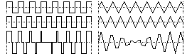 The diagram shows the resultant waveforms. The top and middle waves are the two individual detuned waves, while the bottom wave is the added result. The left shows 2 detuned Square waves added together and the right shows 2 detuned Tri-waves added together.
The resultant waveform is quite dynamic. It changes over time, due to the interference of the detuning. This evolution of waveform over time gives a sense of movement to the timbre because of the "phase" differences. Sometimes the two waves are in-phase (ie both going up at the same time) and sometimes they are out-of-phase (ie one going up and one going down). Mostly, it's something in between.
Note that, when they are in-phase, the resultant amplitude is strong (ie it is loud) and, when it is out-of-phase, the resultant amplitude is weak (ie it is quiet). This will cause a bit of "tremolo" or beating of amplitude (The greater the detuning, the faster the rate or speed of the tremolo). The tremolo effect can be reduced by making one oscillator louder than the other.
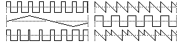 SYNC - Sync is where the cycle of one oscillator (the synchroniser) is used to synchronise or "reset" the oscillator of another (the slave). The top right hand graph shows a Saw wave before sync, the middle right graph shows the synchroniser (in this case a Square wave at a lower frequency), and the bottom right graph shows the effect of synchronisation. As the Square wave completes each cycle, the Saw wave is "reset" to start again. This results in a new static wave whose frequency is that of the synchroniser but whose shape is a portion of the original. Note that the choice of wave for the synchroniser is irrelevant and only it's frequency matters.
Applying Principles to Other Synthesizers
With sampling and digitised waveforms, there are now more alternatives to the simple mathematical waveforms. Let us look at how the subtractive synthesizer process applies to these:
DIGITISED WAVEFORMS - A digitised waveform (sometimes referred to as Pulse Code Modulated [PCM] waveform) is a waveform stored in a memory chip. It may originate from a sample (ie real sound) or it could be created. Typically, the waveforms stored would be single cycles only. Put tons of these digitised waveforms on a memory chip and you have the makings of a wave-table synthesizer.
The quality of the digitised waveform will depend on the Resolution and Rate (as well as the inherent quality of the sound itself). Compact Disk quality uses 16-bit resolution and 44.1kHz sample rate.
Resolution of 16-bits means that the sound "amplitude" is captured and stored in levels from 0~65,535 (2^16). On the waveform graphs, this would be the vertical axis. The horizontal axis (time) is captured by the sample rate. A sample rate of 44.1kHz means that 44,100 of the amplitude "levels" (0~65,535) are taken per second.
PHASE DISTORTION - This is a synthesis method popularised by Casio's CZ-101 and other CZ-synths. Although it is not a subtractive synth, it can actually be treated as one. A CZ-synth basically has 3 envelopes for DCO (pitch), DCW (distortion), and, DCA (amplifier). Phase Distortion relies on "reading" the digitised waveform in a non-linear way. Normally, when you play a digitised waveform, the processor "reads" the data at the intended rate (eg 44.1kHz). A Phase Distorted "reading" would be where the part of the data is read at one rate and the remainder at another rate (eg first half at 22kHz and the second half at 66.2kHz [average = 44.1kHz]). This distorted data-reading in effect changes the waveform. In theory, you get a brand new waveform. In practice, it sounds a lot like a LPF at work.
OTHER SYNTHESIS ENGINES - In a lot of cases, the principles of subtractive synthesis will still apply. Many new synthesizers will still include a Filter of some sort because it is a simple and easy method of controlling timbre. However, this article has not been about filters only. When encountering a new synthesis engine, the principles of Waveforms, Envelopes and Modulation will still apply. With new synths, the challenge will be learning the routing and modulation processes available. But this is true of the older analogue synths too. Learning to control a synth has much to do with familiarisation of the synth layout and how it works. There are no short-cuts. In the end, it's still about knowledge, experimentation and imagination.
For a familiarisation of a selection of synthesizers, see Synthesizer Layouts.